creo 3 trace drawing 3d
To create a 3D model in SketchUp, you're constantly switching amongst the drawing tools, views, components, and organizational tools. In this article, y'all detect several examples that illustrate ways yous tin can use these tools together to model a specific shape or object.
The examples illustrate a few of the different applications for creating 3D models in SketchUp: woodworking, modeling parts or abstract objects, and creating buildings. The examples are loosely ordered from the simple to the circuitous.
Table of Contents
- Drawing a chair
- Drawing a basin, dome, or sphere
- Creating a cone
- Creating a pyramidal hipped roof
- Modeling a building from a footprint
- Creating a polyhedron
Drawing a chair
In the post-obit video, y'all see iii ways to draw a 3D model of a chair. In the outset 2 examples, you see two methods for creating the aforementioned chair:
- Subtractive: Extrude a rectangle to the height of the chair. And so utilize the Push button/Pull tool (
 ) to cut away the chair shape.
 - Additive: Start by modeling the chair seat. Then extrude the back and the legs with the Push/Pull tool.
In the third instance, you see how to create a more than detailed and complex model, using components to simplify modeling the chair legs and rungs on the back of the chair.
Tip: You lot tin can use the tips and techniques demonstrated in these chair examples to create all sorts of other complex 3D models.
Drawing a bowl, dome, or sphere
In this example, you expect at one style to describe a basin and how to apply the technique for creating a bowl to a dome or sphere.
In a nutshell, to create bowl, you lot draw a circumvolve on the ground airplane and a profile of the bowl's shape directly above the circle. Then you use the Follow Me tool to turn the outline into a bowl past having it follow the original circle on the ground airplane.
Here's how the procedure works, footstep-by-step:
- With the Circumvolve tool (
 ), draw a circle on the ground plane. These steps are easier if you start from the cartoon axes origin signal. The size of this circle doesn't matter.
 - Hover the mouse cursor over the origin so that the cursor snaps to the origin and then motility the cursor up the blueish axis.
- Starting from the blue axis, depict a circumvolve perpendicular to the circle on the ground plane (that is, locked to the cerise or green centrality). To encourage the inference, orbit and then that the green or ruby-red axis runs approximately left to right along the screen. If the Circumvolve tool doesn't stay in the light-green or crimson inference direction, press and concord the Shift key to lock the inference. The radius of this 2nd circle represents the outside radius of your basin.
- With the Offset tool (
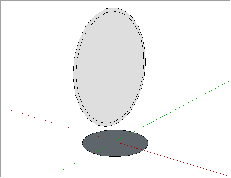
 ), create an start of this second circle. The offset distance represents the basin thickness. Bank check out the following figure to meet how your model looks at this point.
- With the Line tool (
 ), draw two lines: ane that divides the outer circle in half and one that divides the inner circle that y'all created with the Offset tool.
 - With the Eraser tool (
 ), erase the top half of the second circle and the face up that represents the inside of the bowl. When you're done, you have a profile of the bowl.
 - With the Select tool (
 ), select the edge of the circle on the ground plane. This is the path the Follow Me tool will apply to complete the basin.
 - With the Follow Me tool (
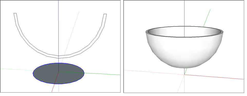
 ), click the profile of the bowl. Your bowl is complete and you can delete the circle on the basis plane. The following figure shows the bowl profile on the left and the bowl on the right.
Note: Why exercise you lot have to draw two lines to divide the offset circles? When you depict a circle using the Circle tool (or a curve using the Arc tool, or a curved line using the Freehand tool), you are really cartoon a circle (or arc or curve) entity, which is made of multiple-segments that act like a single whole. To delete a portion of a circle, arc, or curve entity segment, yous demand to pause the continuity. The kickoff line y'all describe creates endpoints that pause the segments in the outer circle, but not the inner circumvolve. Cartoon the second line across the inner circumvolve breaks the inner circle into 2 continuous lines.
You can use these same steps to create a dome by just drawing your profile upside down. To create a sphere, you don't need to modify the second circle to create a profile at all. Bank check out the following video see how to create a sphere.
Creating a cone
In SketchUp, you can create a cone by resizing a cylinder confront or by extruding a triangle along a round path with the Follow Me tool.
To create a cone from a cylinder, follow these steps:
- With the Circle tool, describe a circumvolve.
- Utilize the Push button/Pull tool to extrude the circle into a cylinder.
- Select the Movement tool (
 ).
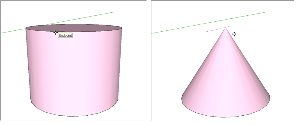
). - Click a key point on the top edge of the cylinder, as shown on the left in the figure. A cardinal bespeak is aligned with the red or greenish axis and acts as a resize handle. To notice a cardinal indicate, hover the Move tool cursor around the edge of the top cylinder; when the circle border highlighting disappears, this indicates a primal point.
- Move the edge to its center until information technology shrinks into the bespeak of a cone.
- Click at the center to complete the cone, equally shown on the left in the figure.
Hither are the steps to model a cone by extruding a triangle along a round path:
- Draw a circle on the footing plane. You'll discover it's easier to align your triangle with the circle's middle if you start drawing the circumvolve from the axes origin.
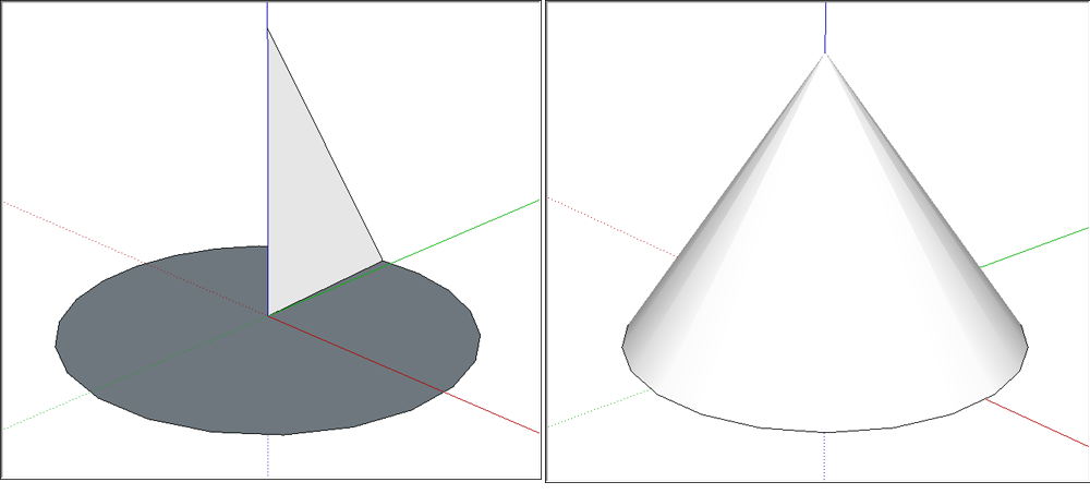
- With the Line tool (), draw a triangle that's perpendicular to the circle. (See the left image in the following figure.
- With the Select tool (), select the confront of the circumvolve.
- Select the Follow Me tool () and click the triangle face, which creates a cone well-nigh instantaneously (every bit long every bit your estimator has the sufficient memory). You tin come across the cone on the right in the following effigy.
Creating a pyramidal hipped roof
In SketchUp, you can easily depict a hipped roof, which is just a elementary pyramid. For this instance, you encounter how to add together the roof to a simple 1-room firm, too.
To draw a pyramid (pull upward a pyramidal hipped roof):
- With the Rectangle tool (
 ), describe a rectangle large enough to encompass your building. To create a true pyramid, create a square instead of a rectangle. The SketchUp inference engine tells you when y'all're rectangle is a square or a aureate section.
 - With the Line tool (), draw a diagonal line from one corner to its opposite corner.
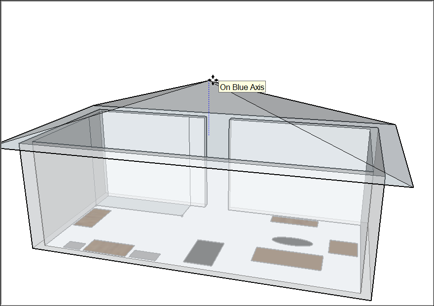
- Draw another diagonal line from i corner to another. In the effigy, you lot run into how the lines create an X. The example shows the faces in X-Ray view so you can see how the rectangle covers the floor program.

- Select the Movement tool () and hover over the center point until a green inference point is displayed.
- Click the centre point.
- Motion the cursor in the blue management (up) to pull up the roof or pyramid, as shown in the figure. If you lot need to lock the move in the blue management, press the Up Pointer cardinal as you move the cursor.
- When your roof or pyramid is at the desired height, click to finish the movement.
Tip: When you're creating a model of house or multistory edifice, organize the walls and roof or each floor of your building into separate groups. That way, y'all tin can edit them separately, or hide your roof in lodge to peer into the interior floor plan. See Organizing a Model for details most groups.
In SketchUp, the easiest way to first a 3D edifice model is with its footprint. After y'all accept a footprint, you can subdivide the footprint and extrude each section to the correct height.
Here are a few tips for finding a building's footprint:
- If you're modeling an existing edifice, trace the outline of the building with the cartoon tools. Unless the building is obscured by trees, you lot can find an aerial photo on Google Maps and trace a snapshot. From within SketchUp, you tin can capture images from Google and load them straight into a model, every bit shown in the following effigy.
- If y'all don't have an aeriform photo of the existing building yous want to model, you may need to endeavor the old fashioned route: measuring the exterior to create the footprint and drawing the footprint from scratch. If literally taking measurements of an unabridged building is impractical, yous can use tricks such as using the measurement of a single brick to judge overall dimensions or taking a photo with an object or person whose length you do know. Encounter Measuring Angles and Distances to Model Precisely for more details.
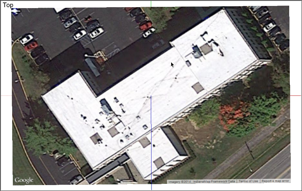
If you're able to start with a snapshot of your footprint, the following steps guide yous through the process of tracing that footprint. First, ready your view of the snapshot:
- Select Camera > Standard Views > Superlative from the card bar.
- Select Camera > Zoom Extents to make sure y'all tin can see everything in your file.
- Use the Pan and Zoom tools to frame a good view of top of the building that y'all want to model. You need to be able to meet the building conspicuously in order to trace its footprint. See Viewing a Model for details about using these tools.
- Choose View > Face Style > X-Ray from the menu bar. In Ten-Ray view, you tin see the top view of the building through the faces that yous describe to create the footprint.
After you set up up your snapshot, try the techniques in the post-obit steps to trace the edifice footprint:
- Ready the drawing axes to a corner of your edifice. See Adjusting the Drawing Axes for details.
- With the Rectangle tool (), describe a rectangle that defines role of your edifice. Click a corner and then click an opposite corner to draw the rectangle. If your building outline includes non–ninety-degree corners, curves or other shapes that yous can't trace with the Rectangle tool, use whichever other drawing tools you lot demand to trace your building's footprint.
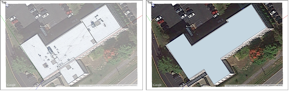
- Continue cartoon rectangles (or lines and arcs) until the unabridged building footprint is defined by overlapping or adjacent rectangles, every bit shown on the left in the following figure. Make certain there aren't any gaps or holes; if there are, fill them in with more rectangles.
- With the Eraser tool (), delete all the edges in the interior of the building footprint. When you're done, y'all should have a single confront defined by a perimeter of directly edges. You lot may want to turn off X-Ray view, equally shown on the right in the following figure, in order to run into your faces and concluding footprint clearly.
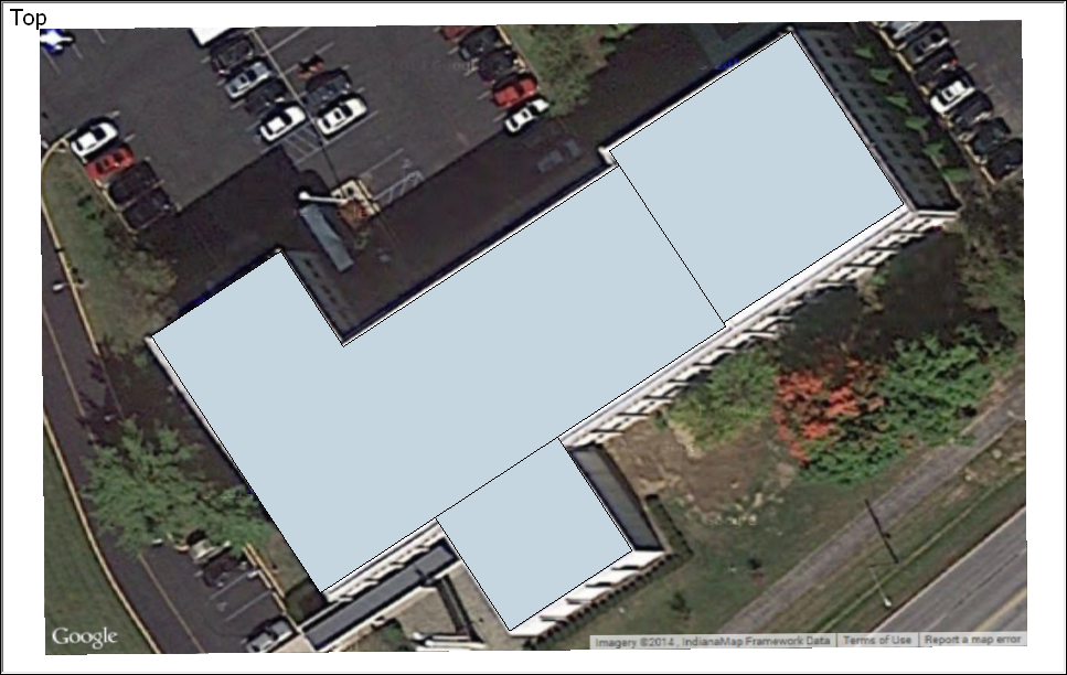
- Some elementary buildings have a single exterior wall height, but most have more one. After y'all consummate the footprint, use the Line tool to subdivide your building footprint into multiple faces, each respective to a different exterior wall height, as shown in the post-obit effigy. Then, you can employ the Push/Pull tool () to extrude each area to the correct building height.
Creating a polyhedron
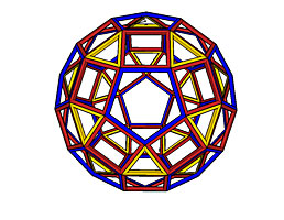
In this instance, you run across how to create a polyhedron, which repeats faces aligned effectually an axis.
To illustrate how you lot tin create a complex shape with basic repeating elements, this instance shows you how to create a polyhedron called a rhombicosidodecahedron, which is fabricated from pentagons, squares, and triangles, equally shown in the figure.
The following steps explain how to create this shape past repeating faces around an axis:
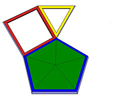
- Constitute the right bending betwixt the first square and the pentagon, and betwixt the kickoff triangle and the square. See Measuring Angles and Distances to Model Precisely for details about measuring angles with the Protractor tool.
- Mark the verbal middle indicate of the pentagon, which is shown hither on a green surface that has been temporarily added to the pentagon component. This is the axis effectually which the copies volition be aligned.
- Make the square and triangle components, and and then group the ii components. For details about components, see Developing Components and Dynamic Components. To learn virtually groups, see Organizing a Model.
- Preselect the objects that you want to re-create and rotate (in this example, the group you just created).
- Select the Rotate tool (
 ).
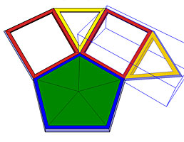
). - Align the Rotate cursor with the pentagon face up and click the center indicate of the pentagon, every bit shown in the post-obit figure.
- Click the Rotate cursor at the point where the tips of the foursquare, triangle, and pentagon come together.
- Printing the Ctrl key to toggle on the Rotate tool's copy function. The Rotate cursor changes to include a plus sign (+).
- Motility the cursor to rotate the pick around the centrality. If you originally clicked the signal where the tips of the foursquare, triangle, and pentagon came together, the new group snaps into its new position, as shown in the following figure.
- Click to end the rotate performance.
- Go along rotating copies effectually the axis until the shape is consummate. As you lot build the rhombicosidodecahedron, yous need to group different components together, and rotate copies of those groups around various component faces.
Tip: If the component yous are rotating effectually is non on the reddish, light-green, or bluish plane, make sure the Rotate tool's cursor is aligned with the face of the component before you lot click the center bespeak. When the cursor is aligned, press and concur the Shift key to lock that alignment as you lot move the cursor to the eye point.
Source: https://help.sketchup.com/en/sketchup/modeling-specific-shapes-objects-and-building-features-3d
0 Response to "creo 3 trace drawing 3d"
Postar um comentário